Introduction
This web page guides in programming the STM32F0 ARM microprocessor series. The aim is to provide a compelling, easy to use method using an open source toolchain setup next to the commercially available products like Keil, mbed, etc. The setup can be summarized as making use of:
- STM32F0 (ARM Cortex M0) MCU (STM32F051 specifically), soldered on a breakout board
- Debian based (e.g. also Ubuntu, Mint, Raspbian, etc).
- GNU gcc standard compiler
- For flashing: openocd with a Raspberry Pi as SWD JTAG adapter
- Standard STM library STM32F0Cube
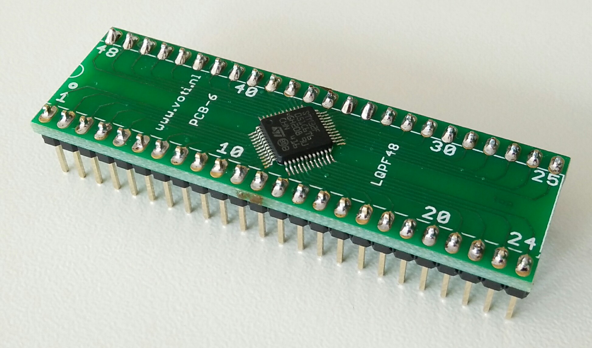
A note here on packaging and soldering: the STM32 MCU's are not available in DIP packages, but soldering Surface Mound Technology Devics (SMT's) is relatively easy. It's is worthwile to be able to solder SMT, wich opens up a wealth of other Integrated Circuits to be used in your projects. In oder to learn SMT soldering, there are plenty of tutorials on Youtube and elswhere on the internet explaining how to do it. A standard soldering iron, solder, and solder flux will do. To get started, it is worthwile to explore the different sizes in which MCU's can be ordered. The STM32F051 is available for instance in 48-pin LQFP48 package, which has a pitch of 0.5mm between the pins, but also the LQFP32 version with a pitch of 0.8mm and easier to begin with. There are also TSSOP20 MCU's like the STM32F030, which are dual in line with a pitch of 0.65mm. Below a picture of the MCU used in this example, soldered on a standard PCB
Raspberry Pi as SWD JTAG Adapter
In this case, the Raspberry Pi Zero W (wireless) is used to program the MCU. This is an even more convenient and budget friendly method than using the FT232H used previously as a USB to UART modem, but for rerference, see this tutorial on programming the LPC1114 using this modem. So how does this work? The Raspberry Pi's GPIO's can be used to send and receive the JTAG Servial Wire Debug signals to and from the STM32, using the openocd software package. The advantage here, is that next to being budget friendly (the Raspberry Pi Zero Wireless retails as low as $10), the Pi itself acts both as compiler / debugger, and interfaces directly to the STM32. This, opposed to using a USB to UART modem, which requires connecting to the model via USB (and additional issues with drivers). All subsequent commands below are executed on the Raspberry Pi itself, either remotely via ssh making use of the wireless connection for headless setups (e.g. using Raspbian Lite), or directly via keyboard/mouse/monitor connected to the Pi.
Setting up the GNU Toolchain
The set of programs used to compile and flash code to a microcontroller is named toolchain. As of writing, the standard GNU compiler toolchain can be used to compile source code into executable binaries. In order to obtain the toolchain it is cimply a matter of installing the correct package. On Debian, and Debian-based distributions like Ubuntu, Mint, Raspbian, etc, this can be done either via a package manager like Synaptic (which is a front-end for apt), or using apt directly on the command line:
sudo apt-get install gcc-arm-none-eabi
Some background here: a special version of the gcc compiler is required for compiling code for a target processor other than the host computer. This is called cross-compiling. That explains the gcc-arm version of the compiler. The “none” version is needed to indicate the use without an operating system (also known as baremetal programming). If we were to compile a program used for an OS, some parts of the program can / should make use of the OS provided functions, for instance when allocating and referencing memory. Without an OS, these standard function need to be linked and added to the binary you are compiling. This will also install the other required packages like binutils and the c-library.
Next to this, in order to flash your binary to the MCU, openocd will be installed:
sudo apt-get install openocd
There are some caveats on "older" Debian based versions of openocd, see this extensive tutorial about obtaining the correct version.
Acquire the STM32F0 libraries
The example used here, makes use of the open source libraries provided by STM for the selected MCU. These can be downloaded from the STM site directly, or by downloading the same library via the created git repository. The latter also requires the git package to be installed:
sudo apt-get install git
after which the STM32 library can be cloned:
git clone https://github.com/catch22eu/STM32Cube_FW_F0
Connect the Raspberry Pi with the STM32
See the picture below on how to hook up the Raspberry Pi to the STM32:
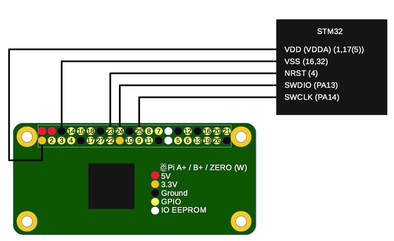
On Raspberry Pi side, following pins are used:
- Ground (any convenient ground pin)
- 3.3V pin (any of the two available 3.3V pins)
- GPIO pin 23: nReset signal
- GPIO pin 24: SWDIO signal
- GPIO pin 25: SWCLK signal
The STM32 (in this case the 32pin STM32F051) pins:
- pin 16 and 32: Ground
- pin 1, 5, 17: 3.3V (for both VDD pins and the VDDA pin)
- pin 4: nReset signal
- pin 23: SWDIO signal
- pin 24: SWCLK signal
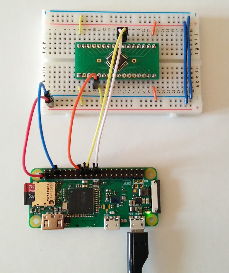
This is a bare-minimum wiring diagram for this mcu (not making use of any decoupling capacitors, but seems to be working anyway). Refer to the STM32 Getting Started hardware Development guide for more details. Using a breadboard and some jumper wires, a practical setup in the end looks like this:
Hello World Example (Blink LED)
The source code of the example below can now also be installed on the Raspberry Pi (without changing directory) from the previous command:
git clone https://github.com/catch22eu/STM32F051_BlinkLED
Then cd into the downloaded directory:
cd STM32F051_BlinkLED
Relevant file is the main.c file here, which is compiled and downloaded onto the STM32 (and makes use of the STM32F0 Libraries downloaded earlier):
#include "stm32f0xx_hal.h"
#include "stm32f0xx_hal_rcc.h"
#include "stm32f0xx_hal_gpio.h"

#include "stm32f0xx.h"

void delay (int a);

void gpio_init();

int main(void)
{
	// Enable the GPIO AHB clock, and init GPIO
	__HAL_RCC_GPIOB_CLK_ENABLE();
	gpio_init();

    while (1)
    {
		HAL_GPIO_TogglePin(GPIOB,GPIO_PIN_1);
        delay(500000);
	}
    return 0;
}

void delay (int a)
{
    volatile int i,j;

    for (i=0 ; i < a ; i++)
    {
        j++;
    }

    return;
}

void gpio_init()
{
	GPIO_InitTypeDef GPIO_InitStruct;

	GPIO_InitStruct.Pin = GPIO_PIN_1;
	GPIO_InitStruct.Mode = GPIO_MODE_OUTPUT_PP;
	GPIO_InitStruct.Pull = GPIO_PULLUP;
	GPIO_InitStruct.Speed = GPIO_SPEED_FREQ_MEDIUM;
	HAL_GPIO_Init(GPIOB, &GPIO_InitStruct);
}
Note that apart from the main.c file, this also provides other files needed. One of them is the makefile itself, which contains all commands to compile and link with references to the needed libraries. An other important file is the linker script, and the openocd.cfg file.
Run the make command as root to compile and upload the exmaple code to the STM32. Root is required for the openocd upload to work:
sudo make
A blinking LED together with a suitable resistor between GPIO PB1 and ground (pin15 and 16 on the LQFP32 version) should now show all succeeded.