Robot Building
Introduction
Most important part in building a simple robot is planning ahead. Every hour spend in thinking how to construct the robot, which materials and tools will be used, can save a lot of problems during the building phase. To reduce the risk of waisting time, experiments can be performed about the unknowns before the robot is built. For example, the way how the legs of the robot are attached to the servos without using hinges was first tested using wire, but wire proved to be too weak for holding the weight of the robot. Therefore, thick sheet metal is used in the robot which is stiff enough. The next sections describe how the robot was build as kind of a tutorial.
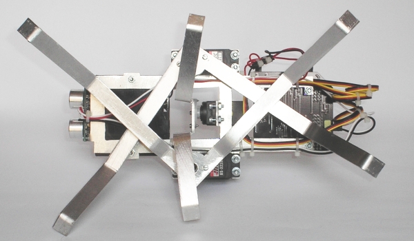
Figure 1: underside of the robot.
Robot Building Tools
The challenge of this robot is to build it without
professional tools. Of help here as well is aluminum, which is
an easy robot building material to work with. It's easy to
drill, cut or saw, and has the "high tech" look and
feel compared to other materials sometimes found in robots like
wood.
For drilling, an ordinary electric drill is used with HSS
(which stands for High Speed Steel) drill bits. To mark the
center location of the hole, a center punch is a very handy
tool to make a little dent in the aluminum. With this dent, the
drill is prevented from wandering off causing inaccurate
placement of the hole.
A coping saw is used to cut the sheet, and a set of pliers to
bend the sheet. For the electronic part of the robot, a
multimeter is a must-have, as well as a soldering iron. In this
robot design, no tools were used to make crimps, although to
make thing neat, it's recommended to make your own crimps.
Summing it up, following tools are used:
- Electric drill with HSS drill bits
- Center punch
- Hammer
- Coping saw
- Files
- Pliers
- Multimeter
- Soldering iron
How to Make a Simple Robot Body
To get an idea of the size of the robot, all robot parts
were laid out on a table the way they would be placed with
respect to each other. After some shifting, a good robot layout
was found, and the arrangement was sketched on aluminum sheet.
For this robot size, 1.4mm thick sheet fits well with the
relatively small design of this robot. Building larger robots,
requires thicker sheet. With this sketched layout, the contours
of the robot body were sketched on the sheet.
A coping saw was used to cut the metal. This went remarkably
well, it took approximately two hours to make the robot body as
shown in the pictures. A flat file was used to remove burrs and
sharp edges, and to straighten out the curved edges. A 3mm
drill was used for drilling the holes. A note about safety
here: be careful with drilling holes in sheet metal. The drill
can get jammed easy, especially with thin sheet and large
diameter drills. When holding the metal sheet stable, the sheet
can spin around rapidly when this happens, and acts like a
knife. Use a bench press, or something fixed to the table to
prevent the sheet from spinning counterclockwise. Never hold
sheet metal by hand when drilling.
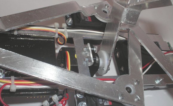
Figure 2: Detail of how the legs are attached to the
servos.
As can be seen in the picture above (Figure 2), the
middle robot servo is positioned with a 90 degree angle to the
robot frame. Therefore, part of the robot frame had to be bent
to mount the servo. A pair of pliers and some pieces of
aluminum sheet were used to experiment with bending the sheet.
Aluminum of this thickness results in a 3mm radius at a 90
degree angle. This means the holes need to be pretty close to
the bending radius in order to line up with the mounting holes
of the robot servo.
Easy Attachment of Legs to R/C Servos
On the Internet, the principle to attach brass wires with
paper clip wire to the servo wheels to act as legs can be
found. This method is simple, but unfortunately the brass wires
were not stiff enough to carry the weight of the robot.
It's probably a good way to construct robot legs for
smaller size robots, for instance when mini-servos and smaller
batteries are used. Even 1mm tick aluminum plate was not stiff
enough to act as legs, and finally a 2mm aluminum plate was
found strong enough to carry the robot's weight.
Using a center punch to mark the hole before drilling is
accurate enough for drilling the 2mm holes using an ordinary
portable drill. The challenge was
to drill holes of 8-9mm for for the servo wheels to fit in, see
again Figure 2.
Because the drill diameter is so large compared to the sheet
thickness, the drill jams into the sheet very easy.Last part of
the 9mm holes were filed away using a round bastard file.
Robot Assembly
All parts were attached to the robot frame, and the
electrical wiring tied to the frame using tie wraps, see
Figure 3. Spare servo wires were soldered to the SRF04
ranger, and for making the servo power connection.
For both the SRF04 ranger, and the battery holder, M2.5 sunken
head bolts were used. The robot legs are attached using short
2mm parker screws (the Hitec servos come supplied with screws
used for attaching servo links, but they could not be used for
attaching metal sheet). After shopping some hardware stores, I
came to the conclusion M3 is the minimum size screws in these
kind of shops (in Holland that is), and they usually do not
sell thicker aluminum sheet than 1mm. For smaller sizes screws,
and for thicker sheets, one has to go to a R/C model shop, or
search the Internet and order on line.
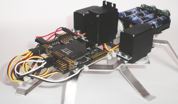
Figure 3: Back side of the robot.
Improve Walking Performance and Ease of Use
Currently, the robot is being tested, and improved by
applying 2 switches to turn on the main power source, and to
disable movement. This is because the only way to switch on and
off the power is to put the batteries in the battery holder.
The servos are immediately energized once the power is up, and
can only be de-energized once user software is loaded, or when
the power is turned off again. The RS232 DB9 connector will be
fixed to the frame to be able to connect the robot easily to
the host computer.
Secondly, the SRF04 ranger detects flat objects well when they
are faced perpendicular to the ranger. When the robot is
walking towards a wall with an angle of approximately 45
degrees or more, the range finder will not detect the wall and
bump into it. Two options are being thought of: adding
microswitches to the robot's body or legs to detect a
collision, or to add a fourth servo to mount the ultrasonic
ranger onto to be able to move rotate the ranger sideways. The
latter is likely to be less complicated.
Robot Building History
1 January '05: The project started January 2005, by
browsing the internet. The first draft of this document was
created around this period as well.
3 August: Ordered parts at Acroname.
7 August: Published this web document.
16 August: Bought saw at toolshop.
20 August: Bought aluminum sheet and copper wire at hobby shop.
Started building the frame.
27 August: Searched for other material for the legs, and for
small size screws.
28 August: Bought aluminum sheet and small size screws at a R/C
hobby shop, finished building the robot.
29 August: Robot made it's first steps using TEA
programming language.
3 September: Made pictures of the robot, and published the
second version of this web document.
6 September: Lowered the robot 2cm. This is revision 2 of the
robot.
23 June '07: Finalized the new web-site.

This robot is featured in robot cafe and startpagina