Introduction
The Beaglebone makes use of the Texas Instruments Sitarra AM335x processor, which is in that sense unique compared to other Single Board Computers in that this processor has next to the main ARM CPU, two additional CPU’s called PRU (Programmable Realtime Units). This architecture accommodates both running a mainline Operating System (thus far the standard is Debian Linux), and use two smaller processors to perform fast, real-time operations. For some this is considered as the sweet spot between Raspberry Pi, which is the popular platform running on a Linux OS (but less capable of doing real-time tasks), and the Arduino (which is great for real-time, but a compromise for connectivity or complexity). The Beaglebone has both advantages of running a modern OS with possibility to interconnect like a computer, but also perform real time operations. The main CPU and PRU's are interconnected with each other with a data bus to communicate and/or share data with each other. Both systems (the main CPU and the PRU’s) can perform GPIO operations as well, allowing for very fast input/output operations. Programming of the PRU cores was first possible by provision of a freely distributed assembler, but later on also by a C/C++ compiler which made programming the real time units more accessible for programmers not familiar with using assembly language. Still, the Beaglebone has a steep learning curve which is hampered by less accessible (and sometimes lacking) documentation, but also by ever changing architecture (like the changes to remoteproc or device tree overlays). This is an attempt to help de-steepen the Beaglebone PRU learning curve, by giving more insight how to write your code in C instead of assembly language.
Some Seemingly Random Notes
There’s two ways to upload code to the PRU’s and communicate between the host CPU and the PRU’s. Originally, the uio_pruss driver was used, but later succeeded by the remoteproc driver. The latter currently only supported by TI, the former still used by the community. There’s another web page how to use the older uio_pruss driver on newer kernels.
Reference to the PRU Software Support Package:
Basic PRU Understanding
There’s two aspects of programming the PRU which in the end turn out to be very easy once understood:
- Register access, see next section.
- R30/R31 registers (see the Blink LED example further below)
Direct Register Access
As an example, let's compare three methods of enabling the IEP timer module in the PRU with an increment value of 1 (meaning, the timer is incremented by 1 each clock cycle). This is done by setting the counter enable bit "CNT_ENABLE" of the GLOBAL_CFG_REGISTER and defining the increment value "DEFAULT_INC" of the same register. Refer to the AM335x PRU ICSS Reference Guide about these register values. Each register is directly addressable as a memory segment, given by the Local Data Memory Map in the Reference Manual. This shows the IEP timer starts at address 0x0002_E000. The memory offset of the GLOBAL_CFG register is 0h (so no offset). Bit 0 of this register enables the counter, and bit 8-11 set the increment value. See also here the AM335x PRU ICSS Reference Guide. In the end, writing 0x11 in Hex to address 0x0002E000 achieves what we want.
The bare-bone assembly way of doing this is using a common register (r1 in this case) and a specific command defined by the PRU assembler to copy this register content to the actual the required register:
mov  r1, 0x0011
sbco r1, C26, 0x0, 2
See this page for an explanation. In brief, this puts the required value 0x11 mentioned earlier in register r1 in the first line, then using the second line with an sbco instruction to copy 2 bytes of register r1 into the register defined by the constant C26, with offset 0x0. The C26 constant is one of the semi hard-coded values into the PRU. It’s a maybe somewhat obscure way to reference a plain memory location. In plain C, this can be done by a single line showing directly what is going on:
(*(volatile unsigned int *) 0x0002E000 ) = 0x0011;
A more advanced way of doing this, is using the PRU Software Support Packages header files:
#include <pru_iep.h>
...
CT_IEP.TMR_GLB_CFG = 0x11;
Note that here the header file pru_iep.h is used, which enables reading and writing to a structure variable. See the next section how this actually is achieved.
How does the C code work "under the hood"?
The PRU C Compiler adds non-standard C "type attributes" to read/write directly to PRU registers. The PRU C/C++ Compiler user guide syntax definition is:
int x __attribute__((cregister("MEM", [near|far]), peripheral));
These definitions can be found in the include header files (like pru_iep.h mentioned above):
volatile __far pruIep CT_IEP __attribute__((cregister("PRU_IEP", far), peripheral));
Note the “CT_IEP” definition, which, again, corresponds to the example above. Here, it can also be seen that the "MEM" resister used is "PRU_IEP", and is the name that corresponds to one of the definitions in the linker command file (typically named AM335x_PRU.cmd). The linker command file is also given in the PRU Software Support Package Examples, like this one. In this file, the IEP registers is defined as:
PRU_IEP : org = 0x0002E000 len = 0x0000031C CREGISTER=26
This exactly matches the base register address of the IEP (in the PRU ICSS Reference Guide, being 0x0002_E000). So in the end this explains the “CT_IEP” part of the instruction.
The complete list of available header files is:
pru_cfg.h
pru_ctrl.h
pru_ecap.h
pru_iep.h
pru_intc.h
pru_uart.h
sys_mailbox.h
sys_mcspi.h
sys_pwmss.h
The header files and the reference manual closely match each other. For instance, here’s a relevant section of the pru_iep.h header file for the IEP example above:
/* PRU_IEP_TMR_GLB_CFG register bit field */
union {
	volatile uint32_t TMR_GLB_CFG;
	volatile struct {
		unsigned CNT_EN : 1;		// 0
		unsigned rsvd1 : 3;		// 3:1
		unsigned DEFAULT_INC : 4;	// 7:4
		unsigned CMP_INC : 12;		// 19:8
		unsigned rsvd12 : 12;		// 31:20
	} TMR_GLB_CFG_bit;
};	// 0x0
And here is the section in the reference manual explaining the register content: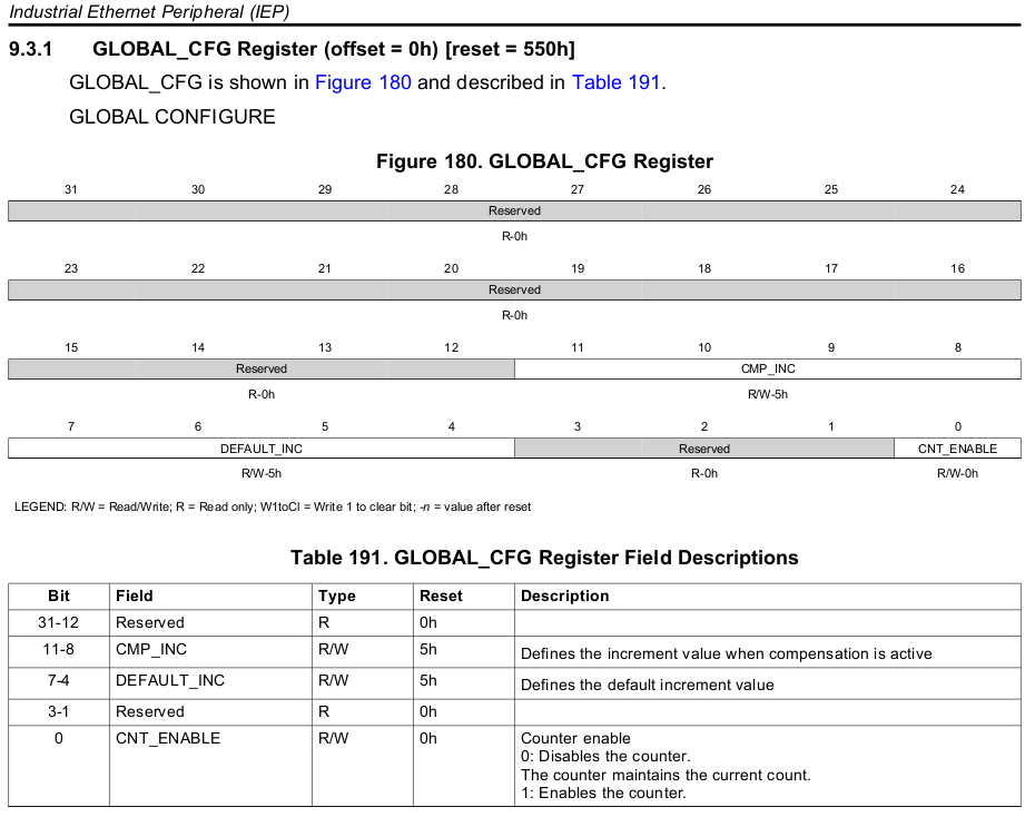
After some comparison, of the two, we can conclude these are exactly the same.
Another Example is the commonly used initialization for the PRU’s, which will be used in the blink LED example below.
CT_CFG.SYSCFG_bit.STANDBY_INIT = 0;
This enables the OCP Master Ports. It's equivalent to the bit-clearing assembly instruction combination found often:
LBCO &r0, C4, 4, 4
CLR r0, r0, 4
SBCO &r0, C4, 4, 4
The C PRU Blink Led Example (Hello World)
So here it is, the PRU C Hello World (Blink a LED) in plain C.
#include <stdint.h>                                     // needed for pru_iep.h
#include "pru_cfg.h"                                    // needed to initialize OCP
#include "pru_iep.h"                                    // needed for pru IEP counter

// See http://elinux.org/Ti_AM33XX_PRUSSv2: P9_25 is set by __R30 bit 7
#define R30_out_bit 7

// Clock cycles to wait (note: PRU's run at 200MHz, so 100M equals 0.5s)
#define wait 100000000

// The PRU registers __R30 and __R31 for GPIO (__R30 used here switch the LED on / off)
volatile register unsigned int __R30;
volatile register unsigned int __R31;

void led_output( char high )
{
    if (high)
                __R30 |= (1 << R30_out_bit );
    else
                __R30 &= ~(1 << R30_out_bit );
}

void reset_iep(void)
{
        // Set counter to 0
        CT_IEP.TMR_CNT = 0x0;
        // Enable counter
        CT_IEP.TMR_GLB_CFG = 0x11;
}

int read_iep(void)
{
        // Return counter content
        return CT_IEP.TMR_CNT;
}

int main(void)
{
        // Initialize OCP (formerly known as ocp_init() in assembly
        CT_CFG.SYSCFG_bit.STANDBY_INIT = 0;

        // variables can not be declared in for loops
        int i;

        // loop a defined amount
        for ( i = 0; i < 5 ; i++)
        {
                // reset the IEP clock
                reset_iep();

                // wait by polling the IEP counter, then switch LED on
                while (read_iep()<wait) {}
                led_output(1);

                // another wait method, then switch LED off
                __delay_cycles(wait);
                led_output(0);
        }

        __halt();

        return 0;
}
Most is explained in the previous paragraphs. New is the introduction of the __R30 register variable, which is a specific reference to something the TI compiler understands, and is used to output to GPIO pins (opposed to __R31, which is used to read input pins).
To get this code to run successfully can be tricky, as it relies on the assumption this is already a skill mastered. To help though, here are some brief hints and tips. As explained, the code includes the header files mentioned, and the AM335x_PRU.cmd memory configureation file. The device tree overlay need to be set correctly, pin P9_25 is used here, and needs to be configures as output mode 5. Beware of course to use a resisor in series with the LED to not damage your board. I'm using uio prussdrv to load code in the PRU's by a separate c program. This is the former way of doing it, as recently remoteproc is used. For uio to work on newer Beaglebone releases, the dts board file needs to be edited to enable uio, and disable remoteproc, see this instruction. I think remoteproc can also be used though, and may be an easier, better supported way. For further help on getting code to run on the PRUss in general, please check resources on Beaglebone.org forum, and elsewhere.
Regarding this post on coding the PRU in C, feel free to comment on the special post about this here on Beaglebord.org Forum!